Speed Key Names: ilock, il
Signals
Two optional digital inputs: <clear>, <set all>, <i1> through <i999>
For each <i> input, one corresponding digital output: <o1> through <o999>
Description
The Interlock symbol latches a given output signal high on the rising edge of its input, while forcing all the other outputs low. Every input has a corresponding output, and each input/output pair is independent of other input/output pairs.
The Interlock symbol remembers the state of the last input that goes high; thus the output will remain high regardless of subsequent changes on its input.
In addition, all outputs are break before make, meaning that the previously activated output will go low before the next output goes high. This logic is convenient in many applications, especially when an Interlock is used to feed the <enable> inputs of multiple Buffer symbols (the break before make property of the Interlock ensures that only one Buffer will be enabled at any time).
The optional <clear> input forces all outputs low.
The optional <set all> input forces all outputs high simultaneously (the only instance where more than one output can be high at one time). This is useful in certain applications involving non-volatile memory, such as to initialize memory using the Analog, Digital, or Serial RAM symbols.
Example: Source Selection Feedback
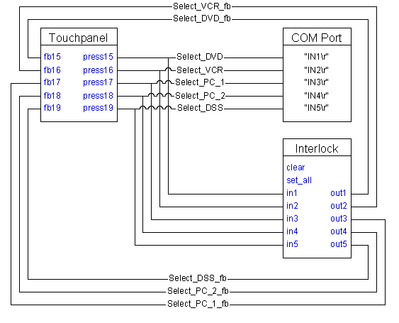
Many audio video systems consist of some sort of source selection. That is, the user can select between a number of sources for viewing and/or listening. A typical example in a conference room application might be VCR, laser disc, slide projector, or computer, which may be selected by sending commands to a switcher or a video projector. Shown below is an Interlock symbol that is implemented to provide feedback to the user by showing which source is currently selected.
Note that the output signals in this example are being used for feedback only, and are not being routed to the switcher to select the source. This is because the outputs of the Interlock are latched, and it is generally considered poor programming to drive momentary functions (such as an RS-232 command) with a latching signal, even though in some cases it may work correctly. Since we have momentary signals already on the input side of the symbol, it is ’r;cleaner’ to use these to drive the switcher.
There is one other reason to use the input signals of the Interlock to drive the switcher, as opposed to the outputs. If we were to use the output signals, and for some reason the same source had to be reselected (if for example, someone manually changed the switcher), this would not work unless another source was selected first and then the desired source reselected. This is because the RS-232 driver will send data on the rising edge of the driving signals, and once an output of an Interlock has gone high, it will not provide a positive-edge unless it is first turned off (by selecting another input) and then turned back on again.
Example: Multi-device control - Each IR Driver symbol represents a different .IR file to control a different device

In the Buffer Examples topic we discussed controlling multiple devices with a common set of buttons using Buffer symbols. At the time, we simply accepted that appropriate signals were generated to enable or disable the Buffers, thus ensuring that only one of them was enabled at any given time. Now that we have introduced the Interlock symbol, we can complete this example as shown above.
See also Memory Interlock