AND
: &
|
Signal name and type
|
Description
|
|
Digital inputs: <i1> through <i999>
|
The inputs that are AND-ed together to determine the state of <out>, as follows:
If all the inputs are high simultaneously, <out> will go high; otherwise, if any input is low, <out> will be low.
High/1 (level sensitive) = Evaluate as true; Low/0 = Evaluate as false
|
|
Digital output: <out>
|
Indicates that all digital inputs are high simultaneously. The output remains high for as long all inputs are high (that is, for as long as the result of the AND evaluation is true). If any digital input is low, this drives the output low.
In the example below "Signal_out" would be high only when "Signal_1_in" AND "Signal_2_in" AND "Signal_3_in" are high.
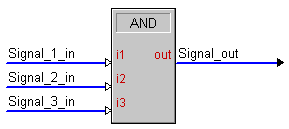
High/1 = Result of AND is true; Low/0 = Result of AND is false
|
AND Symbol Example: Discrete Power On/Off
Because the output of an AND symbol will go high only when all of its inputs are high, you would not ordinarily route multiple button presses directly into an AND. This would mean that both buttons would have to be pressed simultaneously. Instead, one or more inputs to the AND are usually latched signals, often used to determine the current state of something in the system.
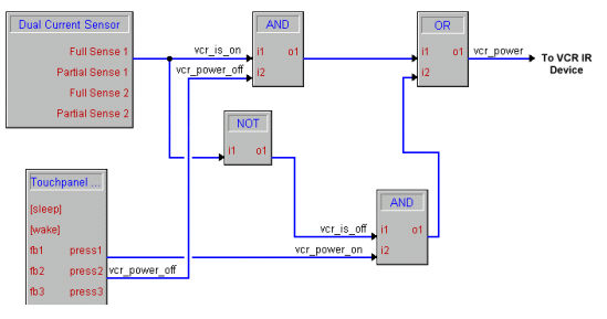
For example, assume that we want discrete power on and off control of an IR-controlled VCR that only provides a toggling power function (on/off). Through the use of a current sensing device, we have generated a digital signal that represents whether a VCR is currently turned on or not. That is, when the signal "vcr_is_on" is high, the VCR is on. Using AND symbols, we can ensure that when the VCR is on and the "vcr_power_off" button is pressed, we send the power command to the VCR. If the VCR is off and the "power_off" button is pressed, we do not want to send the power command because this would cause the VCR to turn on. We use similar logic to handle the case where the "vcr_power_on" button is pressed.
See also NAND, OR, Exclusive OR, Exclusive NOR, NOR