 .
.The Source Routes section of System Designer, allows you to add and configure your controlled devices and to connect their audio inputs/outputs to AV sources in your project. A diagram lets you quickly and easily connect your devices to source switchers and destinations. The media zone audio/video links are a logical concept specifying that a room is using that specific set of amp outputs / displays. Everything else in the source routes diagram is a physical link between the various devices.
Upon selecting the check box preceding the device/location in the Source Routes Tree a graphic image of the device will be displayed in the top-most, left-most corner of the Source Routes Canvas. The device currently selected is outlined in black line/rectangle.
Toggle the device/location check box again to remove it's graphic representation
from the Source Routes Canvas.
To permanently remove the device from your system select it in the Source Routes Tree and choose Delete from the right-click menu
or press .
To move a device to a different location, select the device in the Source Routes Tree and then drag and drop it to its new location.
The device's graphic image displays the inputs and outputs of each device,
called collectively connectors. Connectors are numbered starting from
top left.
For example, the MC3 control system has 4 connectors as shown below: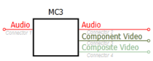
Source Routes allows you to connect Media Sources in four steps:
Add Media Source Devices from the Source Routes Tree to the Routing Diagram.
Connect the Media Devices to switches and/displays.
Connect displays to media-enabled rooms to complete the Routing Diagram.
Use the Auto Layout icon to rearrange the completed Routing Diagram automatically.
Step One: Add Media Source Devices
In the Source Routes Tree, select the check box to the left of the applicable Devices or Rooms to add them to the Routing Diagram:
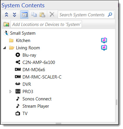
Or, click the AutoLayout smart icon to select all the Devices and automatically add them to the Routing Diagram:

Routing Diagram
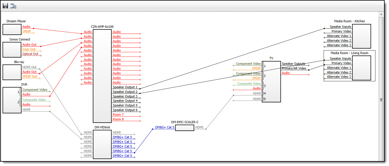
The Devices are added to the right-hand Routing Diagram from left to right based on following device type order of precedence:
Sources
Transmitters
Switcher Input Cards
Switcher
Switcher Adapters
Switcher Output Cards
Room Boxes
Displays
Rooms
The Switcher occupies the approximate center position in the Routing Diagram.
Step Two: Connect Media Sources
Click and hold on a Device's output signal and drag it to another Device's input signal (or input signal to output signal); the signal types must match:
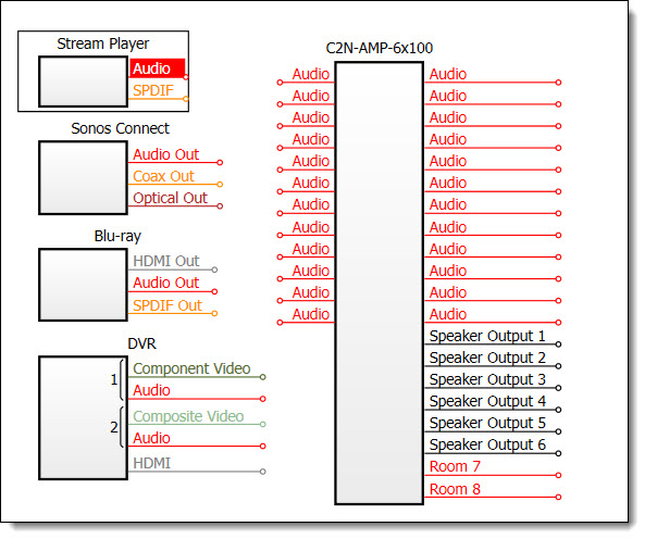
In this example, the Stream Player's Audio output signal has been selected.
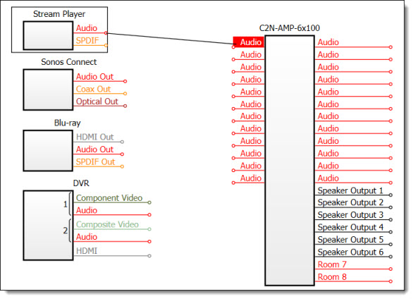
The Stream Player's Audio output signal has been dragged to the C2N-AMP-6x100'S Audio input signal.
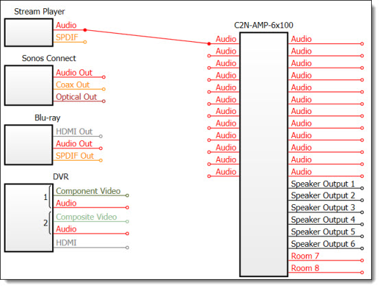
The Stream Players 's Audio output signal has been dragged to the C2N-AMP-6x100's Audio input signal; thereby, completing the Source Route between the two Devices.
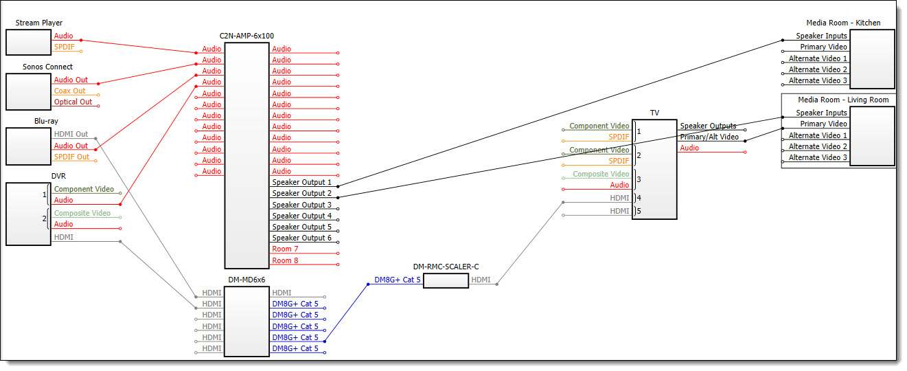
Connect additional Devices to each other, as applicable, until the Routing Diagram is completed.
Sample Source Route - Routing Diagram
Note: To disconnect a Source Route, select the signal and drag it away from the device:
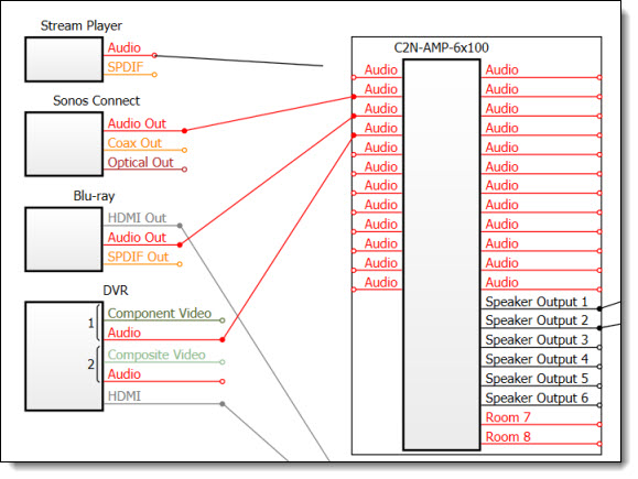
In this example, the C2N-AMP-6x100's Audio input signal was selected and dragged away from the device. When the left mouse button is released, this connection will be deleted.
Step Three: Connect Displays to Media Enabled Rooms
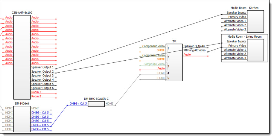
Connect a display to the media enable room:
Step Four: Auto Layout - Rearrange the Routing Diagram
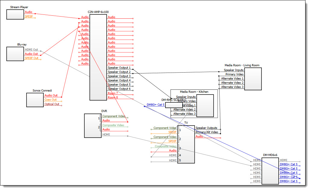
The Routing Diagram can quickly become cluttered and disorganized when Devices are added on the fly and then manually repositioned. This can obscure Source Routes, making them difficult to see, trace, and debug. Use the AutoLayout smart icon to rearrange and organize the Routing Diagram automatically:
Click on the Auto Layout icon:
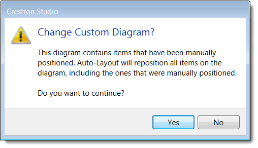
Click on the Yes button in the Change Custom Diagram? dialog box:
This rearranges and reorganizes the Routing Diagram from left to right based on the device type order of precedence noted above.
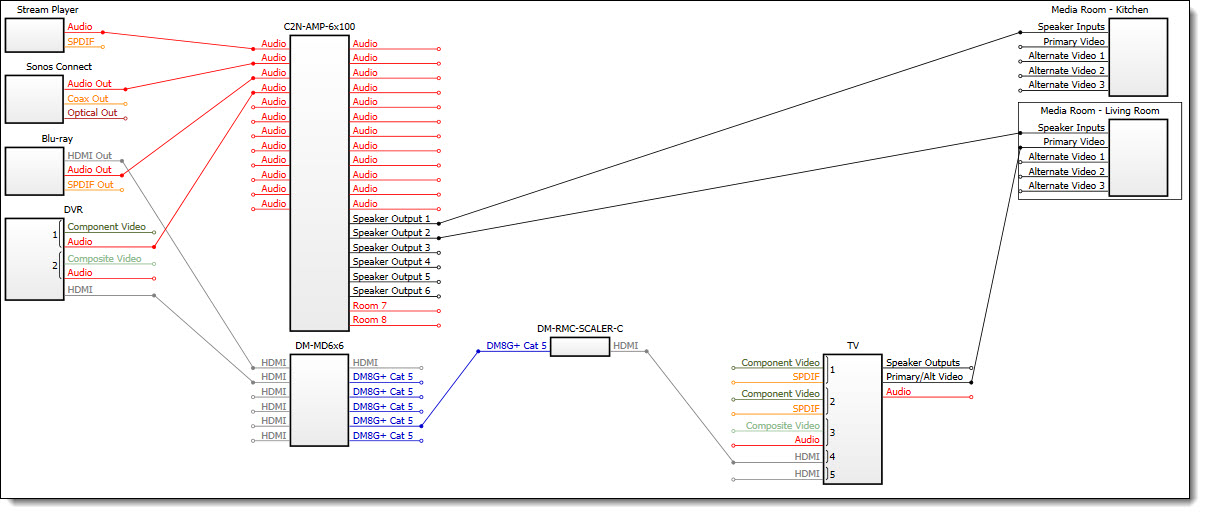
In this above automatically arranged diagram, the Devices were rearranged based on the device type order of precedence. Previously, the DM-MD6x6 was in Column #5 and the Media Room - Kitchen was in Column #3. Now, the DM-MD6x6 now appears in Column #2 and the Media Room - Kitchen appears in Column #5 which is in line with how their signals travel through the Source Route as depicted in the Routing Diagram.
Disconnected devices appear at or towards the bottom of their respective columns:
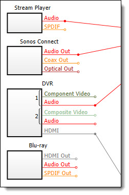
The disconnected Blu-ray device appears at the bottom of its respective column; previously, when connected, it was the third device from the top.
To view the properties for the desired device:
Select the device in
the Source Routes Canvas (selected
device is outlined in a blank rectangle)
-or-
Select the device in the Source Route
Tree (selected device is highlighted in blue)
Click the ShowProperties
To configure the connectors of the selected device:
Select
the device in the Source Routes Canvas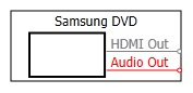
-or-
Select the device in the Source Route
Tree
Select a specific connector and if necessary modify one or more of the following properties:
Group Number - Assign an identical group number
to two or more connectors which have the same direction and are
intended to be used together; otherwise leave the default group
number (the default group number is 0).
Connectors with the same group number and the same direction form
a Connector Group: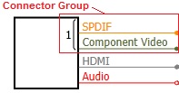
For example, Component video which doesn't carry audio signal is
often coupled together with an Audio component. To signify that
the corresponding connectors are used together, assign the same
group number to the SPDIF digital audio connector and to the Component
Video connector.
Note that all video inputs of Crestron Certified Driver AVRs and a TVs are assigned a group number regardless of whether there is a matching audio connector. Audio connectors are assigned group number only if there is a matching video input type.
NOTE: Although it's possible
to assign the same group number to both input and output connectors,
Crestron Studio®
will treat the Connector Group of inputs and the Connector Group
of outputs with the same number as two different Connector Groups.
Input Name - Specify the name of the input/output.By default, the connector Name for audio and video inputs of Crestron Certified Driver AVRs and TVs are populated by Crestron Studio®
Type (third-party devices only)
- Define the connection type
(HDMI, DVI, etc). The type of the connector of third-party devices
can be changed to match exactly the connector of your device.
Change the connector type by selecting the appropriate type from
the drop down list.
NOTE: By default the connector Types for audio and video inputs of Crestron Certified Driver AVRs and TVs are populated by Crestron Studio®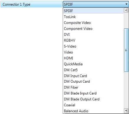
Note:To be able to edit previously
assigned connection type make sure to delete any existing connection
originating from this connector.
Direction
(third-party devices) - Select
a direction (Input or Output) for the connector.
NOTE: Type and Direction
properties are displayed and may be edited for third-party devices
only. Type and Direction for connectors of a Crestron device are
fixed and cannot be changed.
Switching
Command - Specify which switching
command to send to make the device use that connector. The switching
command is ignored if the connector type is set to Output.
NOTE: Crestron Studio® automatically populates the "Standard Command" field for each input connector of Crestron Certified Driver AVRs and a TVs with the correct switching command required to switch to that source. The default switching command can be changed to 'None', to a different device commend, or to use a global macro.
Visible -Clear the Visible check box to remove/hide the connector from the Source Routes Diagram.
To adjust the zoom level of the Source Route Diagram:
You can "zoom in"
to get a close-up view or "zoom out" to see more devices at
a reduced size by pressing  and then turning the mouse scroll wheel forward (zoom-in) or backward
(zoom-out).
and then turning the mouse scroll wheel forward (zoom-in) or backward
(zoom-out).
DM Auto-connectivity
Crestron Studio®
provides auto-connectivity for  supported DM devices, while using the DMNET connectivity option
while adding devices to a project. Upon adding a supported DM Device to
the system its DM inputs/outputs (of type DM
Input Card, DM
Output Card, DM
Cat5, DM Fiber,
DM8G Fiber,
DM8G SM Fiber
and DM8G+ Cat5)
will be automatically connected to corresponding type outputs/inputs
of DM device in the Source Routes Canvas.
supported DM devices, while using the DMNET connectivity option
while adding devices to a project. Upon adding a supported DM Device to
the system its DM inputs/outputs (of type DM
Input Card, DM
Output Card, DM
Cat5, DM Fiber,
DM8G Fiber,
DM8G SM Fiber
and DM8G+ Cat5)
will be automatically connected to corresponding type outputs/inputs
of DM device in the Source Routes Canvas.
Example configuration of a DM-MD8x8 configuration with various input / output cards, TX boxes and RMCs, all of which are automatically connected:
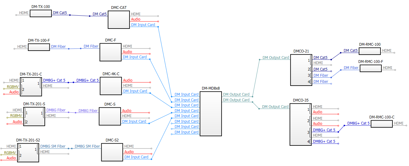
Note that automatic DM connections can be moved (dragged and dropped) to empty slots of the same DM connection type even between different switchers but CANNOT be deleted by using the 'Delete Link' option from the context menu. Moving a connection to a different slot in the Source Routes Diagram updates the slot number/IP-ID of the Device Explorer and the Properties Grid of the device and vice versa.
Systems created in versions of Crestron Studio® 1.35.005 or earlier will be upgraded to DM auto-connectivity on first system open. Existing devices in older system projects will receive model updates and the media connectivity would be fixed (if necessary) to match the physical connectivity.
To create manually a media route between devices:
Note that at this time Crestron Studio® does not provide support for including amplifiers in the Source Route Diagram.
Click the
source and select the desired connector (upon selection the connector
highlights)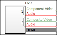
Press the
left mouse key and drag the line to an input of the same type. Note
that Crestron Studio®
will prevent you from connecting incompatible signal types (different
signal types are shown with different colors). For example, composite
video sources cannot be connected to HDMI switcher inputs. Release
the mouse key when the desired input is highlighted. The connection
will be displayed as a line of the same color as the source/input.
The connection properties create virtual links between the devices
in the project to define routes for sources to get to output devices.
All connection properties will be analyzed when the program logic
is generated and will be turned into data for the modules.
Connectors which are already connected to a corresponding input/output
are depicted by a  ;
where no connection exists, the connector is depicted by a
;
where no connection exists, the connector is depicted by a  .
.
Continue creating connections between desired inputs/outputs as needed. Note that if a target input/output already has a source connected, you will have to remove the old connection before you could connect to a different connector (input/output).
Connect the TV's outputs to the corresponding inputs of your Media Room (for example create a connection between the Location Audio Provider output of the TV to the Speakers input of the Media Room; connect the Location Video Provider output of the TV to the Primary Video input of the Media Room). When finished, you will have a graphical representation of your system configuration.
To remove an existing connection (applies to manual connection only):
Select the connection you wish to remove
Right-click the connection you wish to remove and:
Click Delete
Linkfrom the menu: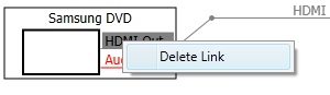
-or-
Press
To save the Source Routes Diagram in an image file:
Press the Save
Source Route Diagram as Image button.
In the Save Source Route Diagram dialog navigate to the desired folder where you wish to save the image file.
Choose File name
for your Source Route Diagram
image. By default the File name
field is pre-filled with the name of your system project.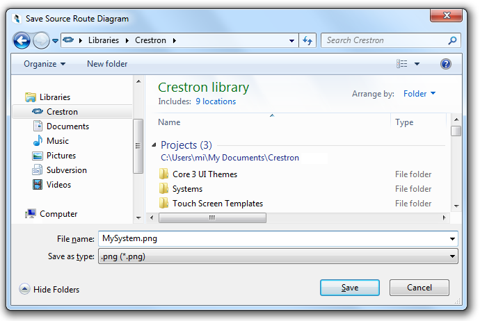
The File Type is set to .png
and cannot be changed.
More:
DM-NVX-350/351(C) Receivers and Transmitters in Crestron Studio®
How to control the volume of C2N-AMP-6x100