How to Create/Edit User Device Modules in SIMPL which are Intended for Use in Crestron Studio®


SIMPL allows the programmer to create several types of user device modules that can then be used successfully to "power" User Devices in Crestron Studio®:

Each SIMPL user device module consists of an Argument Definition, which represents how the symbol will look in SIMPL/Crestron Studio®, and logic symbols. The inputs, outputs and parameters of the Argument Definition are associated with signals and parameters defined in the module.

To create/edit a user device module in SIMPL

Configure the module header

  1. In SIMPL, click the New SIMPL Module button on the toolbar

    - or -
    press

    - or -

    click New SIMPL Module on the File menu.

  2. Edit the ClosedModule Header (accessible by clicking on Edit Program Header on the Project menu when editing existing modules)

    1. On the Module header, click the Device Support tab. Options in the Device Support tab determine which standard commands and templates will be available to the user device SIMPL module.

      Select/modify items from the Device Family, Device Type, Manufacturer and Model lists, or type custom names in the text fields above the lists to match your custom device:
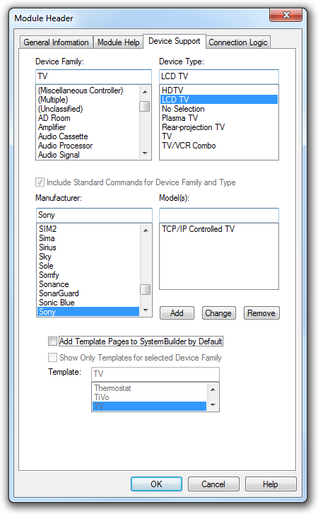
     

      • Device Family: Select the device family from the list, or type a custom name in the corresponding text field. The device family determines the standard commands that can be used with the device.

        If the module is a logic module, i.e. the module is not designed to connect to a device, select "(Logic)" as the device family.

      • Device Type: Select the device type from the list. The device type determines the template pages (if any) that will be used to control the device.

      • Include Standard Commands: Select the check box to automatically add standard commands to the Argument Definition. The standard commands are determined by the selected device family and device type. For example, if the device is a "TV", selecting the check box will add standard transport commands for that device, such as Channel +/-, Volume +/-, Power On and Power Off —to the Argument Definition.

        Note that the "Include Standard Commands" check box is only enabled if the Argument Definition has not yet been programmed. Otherwise the check box will be visible but grayed out.

      • Manufacturer: Select the Manufacturer from the list, or type a custom name in the corresponding text field. If the module is controlling a Crestron device, select "Crestron" as the manufacturer.

      • Model: Type a user-defined model name in the text field and click the Add button. (To remove the model name, select it and click Remove. To edit the name, select it and click Change.)

    1. If creating TCP/IP device, click the Connection Logic tab. Do not select any options in the Connection Logic tab if creating/editing user logic or serial module.
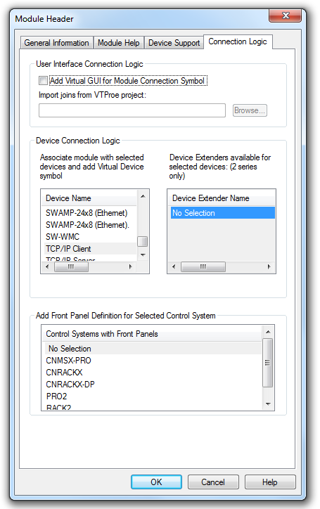

    2. In the Device Connection Logic area, select the TCP/IP Client device from the Device list to add a Virtual Device for Module Connection symbol, which will contain the TCP/IP Client logic and will automatically be connected to the Argument Definition.

    3. Click OK to close the module header.

      Upon closing the module header, a prompt will be displayed that allows you to specify an optional prefix that will added to all signals being used in the default logic. Type the prefix in the text field, or leave the text field blank (for no prefix) and click OK.


  3. Open the Argument Definition in Detail View and expand the symbol to add the required number of inputs, outputs and parameters.

  1. Define the Closedsignal cues.

    To name the inputs and outputs:

    1. Click each signal to highlight it and type the name in the signal field.

    The signal NAMES you type become the signal CUES of the module's symbol.

    • For clarity it is best to arrange the signals by type: digitals, analogs, and serials.

    • Signal cues can consist of letters, numbers or characters, except the comma character (,) and colon character (:). Additionally, signal cues cannot begin with a number.

    You can create a visual space between signal cues by using the special signal name [~UNUSED~].

    Although the [~UNUSED~] qualifier results in a blank space or a gap between the signals in the module's symbol, there is technically still a signal associated with that gap.

  2. Define the Closedparameter fields.

    To define a parameter

    1. Double-click the first available parameter field.

    2. Name the parameter field in the Argument Definition. For example, type "Port" (without the quotation marks) in the parameter field.

  3. Set optional Closedproperties, e.g., default values or add description, for signals and parameter by selecting the signal/parameter and pressing , or right-clicking the signal and selecting Edit Signal/Parameter Properties.

    Specify properties for signals and parameters on the Argument Definition:

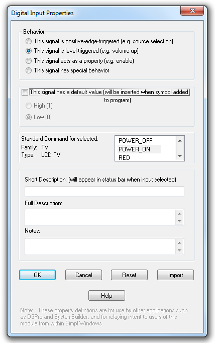
    • ClosedDigital Input Properties


      Behavior

      This signal is positive-edge triggered: Select this option if the command is triggered on the rising edge of the signal.

      A rising edge-triggered digital command will be displayed in Crestron Studio® as a device command preceded by a  icon. This type of command can be assigned as a programming step in the Programming Editor in Crestron Studio®.

      This signal is level-triggered: Select this option if the command is level-sensitive, i.e the signal must be held high for the command to remain active.

      A level sensitive digital command will be displayed in Crestron Studio® as a device command preceded by a  icon. This type of command can be assigned as a programming step in the Programming Editor and allows the Crestron Studio® programmer to specify whether the command will be maintained while the event is active, or for some specified period.
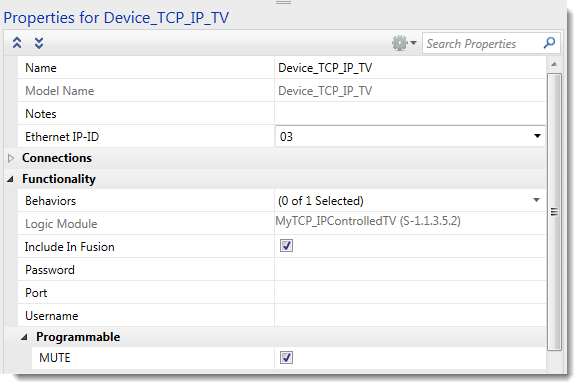
      This signal acts as a property: Select this option if the signal’s state can be set as a property.

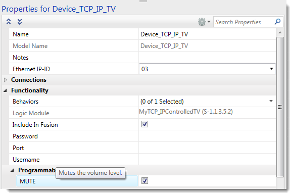
      A digital signal that acts as a property appears in Crestron Studio® as a check box in the Functionality/Programmable section of the Properties Grid of the device:


      The check box is de-selected by default. To instruct Crestron Studio® to display the check box selected by default, click the This signal has a default value (see below) and then choose High/1.

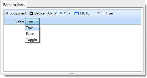
      This digital signal can also be set programmatically to True, False or Toggle as a command step or as an expression in Programming Editor.


      Other events and programming steps can then be triggered depending on the state.

      This signal has special behavior: This option can be selected if the signal doesn't fit into the first three categories. For example, a signal called for a shade motor might have some behavior on the rising edge, different one on the falling-edge, and another one when held high.


      This signal has a default value: If the digital signal should be set to High/1 by default, click this check box and click the desired High (1) or Low/0 radio button. In most applications, however, the default value of the digital signal should be Low (0).


      Standard Commands

      The Standard Commands list box will display the list of all standard commands that apply to the Device Type and Device Family (as specified in the Module Header). Select the appropriate standard command for the input, if it was not already selected.

      Standard commands differ depending on device type. In Crestron Studio® standard commands may be  used for programming DVR  buttons during page generation or to populate the TV's Generic TV Wrapper properties.


      Description

      Short Description: Type a brief description of the signal's functionality.

      If the signal acts as a property, this description will be visible as a tooltip when hovering over the property in the Properties Grid of the device:


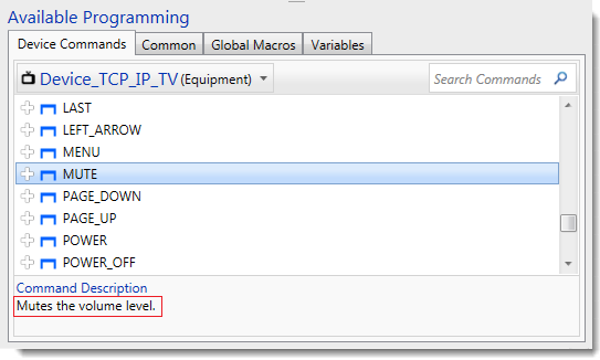
      The same description will also be visible in the Command Description area when the device command is selected in the Available Programming pane:


      Full Description: Type a longer description of the signal’s function and any special behavior the programmer should be aware of. The full description is only visible when the signal acts as a property:


      Notes: Use this text field to give special instructions to Crestron Studio®, in the following format: #KEYWORD <parameter>, with no space allowed after the # character, and the keyword in all caps. Not every keyword takes a parameter.

      Consult the Cue Keyword table for valid keywords that can be entered in the Notes field.


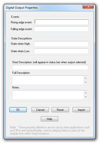
    • ClosedDigital Output Properties


      Events

      Rising edge event: Type a name for the event that will be triggered when a rising edge is seen on the digital output. The event name will be visible in Crestron Studio® in the Events category of the Programmable Events pane in Design & Program.

      Falling edge event: Type a name for the event that will be triggered when a falling edge is seen on the digital output. The event name will be visible in Crestron Studio® in the Events category of the Programmable Events pane in Design & Program.

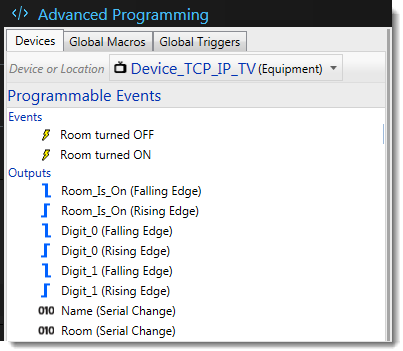
      An output that has been designated as a rising or falling edge event appears in the Events category preceded by a lightning  icon.


      The items listed in the Events category are subsets of those in the Outputs category, which provides a way to present the most typically useful outputs to the Crestron Studio® programmer, i.e. the Outputs category will contain the list of ALL device outputs presented as rising edge and falling edge events, whereas the Events category will contain the specified subset of events.

      For example, if the device output is called Room_Is_On, then the module might define a Rising Edge Event called 'Room turned ON' and a Falling Edge Event called 'Room turned OFF. In Crestron Studio®, the 'Room turned ON' and 'Room turned OFF' events will be visible in the Events category, while the "Room_Is_On" output will be visible in the Outputs category as "Room_Is_On (Rising edge)" and "Room_Is_On (Falling edge)", along with all the other device outputs.


      State Descriptions

      State when high: Type a name for the output state when High/1. The name will be visible in Crestron Studio® in the Property drop-down list in the Conditional Expression Editor when defining a conditional expression and when defining a global trigger.


      State when low: Type a name for the output state when Low/0. The name will be visible in Crestron Studio®  in the Property drop-down list in the Conditional Expression Editor when defining a conditional expression and when defining a global trigger.


      Descriptions

      Short Description: Type a brief description of the output. The Short Description is visible in the Event Description area when the event is selected in the Programmable Events pane:

      Full Description: Type a longer description of the signal’s function and any special behavior the programmer should be aware of.


      Notes: Use this text field to give special instructions to Crestron Studio®, in the following format: #KEYWORD <parameter>, with no space allowed after the # character, and the keyword in all caps. Not every keyword takes a parameter.

      Consult the Cue Keyword table for valid keywords that can be entered in the Notes field.

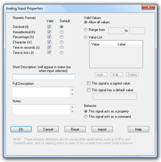
    • ClosedAnalog Input Properties


      Numeric Formats: Select valid formats for the analog value by selecting or clearing the appropriate check boxes.

      Default: Click the radio button that corresponds to the default format.


      Valid Values

      Allow all values: Select this option to allow the full range of analog values (signed or unsigned) for the given numeric format.

      Allow all values: Select this option to allow the full range of values (signed or unsigned) for the given numeric format.

      Range from: Select this option to limit the range of allowable values to a min/max range. Enter the minimum and maximum values in the text boxes.

      Value list: Select this option to present the Crestron Studio® programmer with several value options that represent numeric values. For example, if the allowable range of values is 0d, 1d and 2d, these values can be represented in Crestron Studio® as Off, On and Standby.

      To specify a value to label, click the Add button. Type the numeric (or string) value in the Value field, and then type the label in the Label field and click OK. This will add the value to the Value List. To edit or remove a value select it and click the appropriate button.


      Signed value: Select this check box if the analog value is signed. Otherwise, clear (de-select) the check box if the value is unsigned.

      Default value: Select this check box to enable the text field, and type the default value. This will set the signal to the default value when the command is selected in Programming Editor.


      Behavior

      This signal acts as a property: Select this option to allow the Crestron Studio® programmer to set the value of the signal in the Properties Grid of the device.

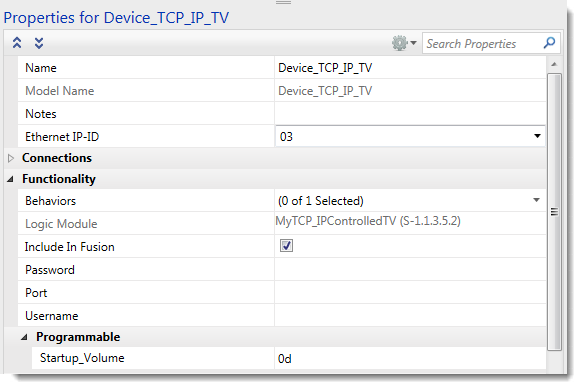
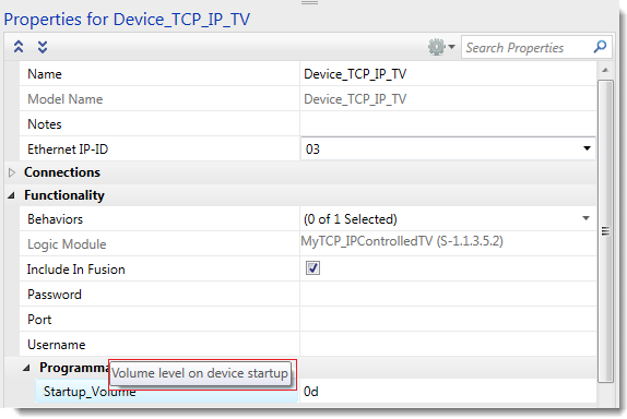
      For example, if an analog input named Startup_Volume is designated as a property, the Crestron Studio® programmer can set the startup volume in the Device Properties Grid without the need to set the volume in the program.

      A digital signal that acts as a property appears in Crestron Studio® as a text field in the Functionality/Programmable section of the Properties Grid of the device:


      This signal acts as a command: Select this option if the analog value should be set programmatically only, and not as a device property.

      An analog signal that is a command or property appears in Crestron Studio® with a red wavy  icon. The value can be set as a programming step in the Programming Editor.
      The value of the signal can also be evaluated against logical operators in a conditional expression in the Conditional Expression dialog.


      Description

      Short description: Type a brief description of the signal's functionality.

      If the signal acts as a property, this description will be visible as a tooltip when hovering over the property in the Properties Grid of the device:


      and in the Description area of the Properties Grid.

      The same description will also be visible in the Command Description area when the device command is selected in the Available Programming pane.

      Full Description: Type a longer description of the signal’s function and any special behavior the programmer should be aware of.


      Notes: Use this text field to give special instructions to Crestron Studio®, in the following format: #KEYWORD <parameter>, with no space allowed after the # character, and the keyword in all caps. Not every keyword takes a parameter.

      Consult the Cue Keyword table for valid keywords that can be entered in the Notes field.

    • ClosedAnalog Output Properties

      An analog output, preceded by a red wavy  icon, is displayed in Crestron Studio® in the Outputs category of the Programmable Events pane in the Design & Program section.


      Numeric Formats: Select valid formats for the analog value by selecting or clearing the appropriate check boxes.

      Default: Click the radio button that corresponds to the default format.


      Valid Values

      Allow all values: Select this option to allow the full range of values (signed or unsigned) for the given numeric format.

      Range from: Select this option to limit the range of allowable values to a min/max range. Enter the minimum and maximum values in the text boxes.

      Value list: Select this option to present the Crestron Studio® programmer with several value options that represent numeric values. For example, if the allowable range of values is 0d, 1d and 2d, these values can be represented in Crestron Studio® as Off, On and Standby.

      To specify a value to label, click the Add button. Type the numeric (or string) value in the Value field, and then type the label in the Label field and click OK. This will add the value to the Value List. To edit or remove a value select it and click the appropriate button.


      This signal is a signed value: Select this check box if the analog value is signed. Otherwise, clear (de-select) the check box if the value is unsigned.


      Description

      Short description: Type a brief description of the signal's functionality.

      The Short Description is visible in the Event Description area when the output is selected in the Programmable Events pane.

      Full Description: Type a longer description of the signal’s function and any special behavior the programmer should be aware of.

      Notes: Use this text field to give special instructions to Crestron Studio®, in the following format: #KEYWORD <parameter>, with no space allowed after the # character, and the keyword in all caps. Not every keyword takes a parameter.

      Consult the Cue Keyword table for valid keywords that can be entered in the Notes field.


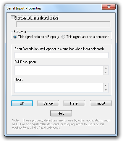
    • ClosedSerial Input Properties


      This signal has a default value: Select this check box to enable the text field, and then enter the default string. The default string will be visible when the Crestron Studio programmer selects the serial command in the Programming Editor.


      Behavior

      This signal acts as a Property: Select this option to allow the Crestron Studio programmer to set the string in the Properties Grid of the device. (The programmer will still be able to specify the string in Design & Program.)

      This signal acts as a command: Select this option if the serial string should be set programmatically only, and not as a device property.

      A serial signal that is a command or property appears in Crestron Studio  preceded by a  icon. The string can be set as a programming step in the Programming Editor and will allow the Crestron Studio programmer to set the value.


      Description

      Short Description: Type a brief description of the signal’s function.

      If the signal acts as a property, this description will be visible as a tooltip when hovering over the property in the Properties Grid of the device.

      The same description will also be visible in the Command Description area when the device command is selected in the Available Programming pane.

      Full Description: Type a longer description of the signal’s function and any special behavior the programmer should be aware of. The full description is only visible when the signal acts as a property.

      Notes: Use this text field to give special instructions to Crestron Studio®, in the following format: #KEYWORD <parameter>, with no space allowed after the # character, and the keyword in all caps. Not every keyword takes a parameter.

      Consult the Cue Keyword table for valid keywords that can be entered in the Notes field.

    • ClosedSerial Output Properties


      A serial output, preceded by a black serial  icon, is displayed in Crestron Studio® in the Outputs category of the Programmable Events pane in Design & Program section.

      Short description: Type a brief description of the signal's functionality.

      The Short Description is visible in the Event Description area when the output is selected in the Programmable Events pane.

      Full Description: Type a longer description of the signal’s function and any special behavior the programmer should be aware of.

      Notes: Use this text field to give special instructions to Crestron Studio®, in the following format: #KEYWORD <parameter>, with no space allowed after the # character, and the keyword in all caps. Not every keyword takes a parameter.

      Consult the Cue Keyword table for valid keywords that can be entered in the Notes field.

    • ClosedParameter Properties


      Parameters are only visible in Crestron Studio® in the Properties Grid of the user device.

      Numeric (16 bit): Select this option if the parameter value is a 16-bit numeric value (signed or unsigned). This will enable the Numeric Formats check boxes.

      Numeric (32 bit):  Select this option if the parameter value is a 32-bit numeric value (signed or unsigned). This will enable the relevant Numeric Formats check boxes.

      String: Select this option if the parameter value is a serial string. This will gray out the Numeric Formats check boxes.


      Numeric Formats

      Numeric Formats: Select the valid formats for the parameter value by selecting or clearing the appropriate check boxes.

      Default: Click the radio button that corresponds to the default format.


      Valid values

      Allow all values: Select this option to allow the full range of values (signed or unsigned) for the given numeric format.

      Range from: Select this option to limit the range of allowable values to a min/max range. Enter the minimum and maximum values in the text boxes. This option only applies to numeric values, not serial strings.

      Value list: Select this option to present the Crestron Studio® programmer with several value options.

      To specify a value to label, click the Add button. Type the numeric (or string) value in the Value field, and then type the label in the Label field and click OK. This will add the value to the Value List. To edit or remove a value select it and click the appropriate button.


      Note that "Value" is numeric if a numeric value is the selected format. Otherwise, if the selected format is a serial string, "Value" vs interpreted as a literal string.

      This parameter is a signed value: Select this check box if the numeric value is signed. Otherwise, clear (de-select) the check box if the value is unsigned.

      This parameter has a default value: Select this check box if you wish to enter default parameter value.


      Description

      Short Description: Type a brief description for the parameter.

      This description will be visible as a tooltip when hovering over the property in the Properties Grid of the device.

      Full Description: Type a longer description for the parameter and any special behavior the Crestron Studio® programmer should be aware of. The Full Description is visible in the Show Description area below the Properties Grid when the parameter is selected in Crestron Studio®.

      Notes: Use this text field to give special instructions to Crestron Studio®, in the following format: #KEYWORD <parameter>, with no space allowed after the # character, and the keyword in all caps. Not every keyword takes a parameter.

      Consult the Cue Keyword table for valid keywords that can be entered in the Notes field.


Program the logic

  1. Add the required logic symbols or modules to the Program View. Use subsystems to organize the programming just as in a standard SIMPL program.

  2. Define the signals and parameters and connect them to their driving sources and destinations.

  3. Connect the signals and parameters in the logic symbols to the associated inputs, outputs and parameters of the Argument Definition.


How do I get my SIMPL module parameter(s) or input(s) to display as a property of my user device in Crestron Studio®?

Generally all module parameters (unless tagged by the #HIDDEN keyword) will be displayed as properties in the Functionality section of the Properties Grid of the user device in Crestron Studio®:
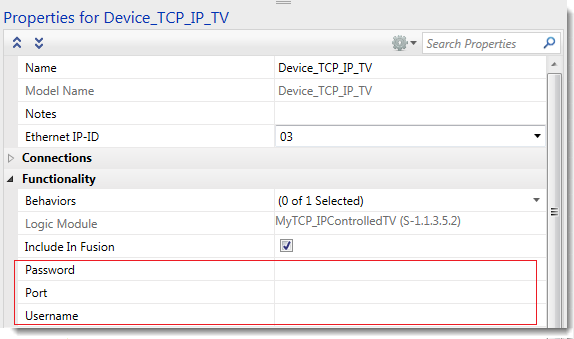
Additionally, any input signals for which the 'This signal acts a property' check box is selected in the Signal/Parameter Properties dialog, will be displayed in the Functionality>Programmable section of the Properties Grid of the user device in Crestron Studio®:


How do I add tooltips to custom properties of my user device to display in Crestron Studio®?

Any text that you type in the Short Description field in the Signal/Parameter Properties dialog of your module parameters and/or input signals for which the 'This signal acts a property' check box is selected, will be displayed as a tooltip when hovering over the corresponding field in the Properties Grid of the user device in Crestron Studio®.


How do I add descriptions to device commands of my user device to be shown in Crestron Studio®?

Any text that you type in the Short Description field in the InputSignal Properties dialog of your module's input signals will be displayed in the Command Description area when the device command is selected in the Available Programming pane:

Similarly, text provided in the Short Description field in the OutputSignal Properties will be displayed in the Command Description area when the event is selected in the Programmable Events pane in Crestron Studio®.


Device Support tab

Options in the Device Support tab determine which standard commands and templates will be avialable to the SIMPL module.

Device Family: Select the device family from the list, or type a custom name in the corresponding text field. The device family determines the standard commands that can be used with the device.

If the module is a logic module, i.e. the module is not designed to connect to a device, select "(Logic)" as the device family.

Device Type: Select the device type from the list. The device type determines the template pages (if any) that will be used to control the device.

Include Standard Commands: Select the check box to automatically add standard commands to the Argument Definition. The standard commands are determined by the selected device family and device type. For example, if the device is a "CD Changer", selecting the check box will add standard transport commands for that device, such as Enter, Eject, Track+/- and Stop—to the Argument Definition.

Note that the "Include Standard Commands" check box is only enabled if the Argument Definition has not yet been programmed. Otherwise the check box will be visible but grayed out.

Manufacturer: Select the Manufacturer from the list, or type a custom name in the corresponding text field. If the module is controlling a Crestron device, select "Crestron" as the manufacturer.

Model: Type a user-defined model name in the text field and click the Add button. (To remove the model name, select it and click Remove. To edit the name, select it and click Change.)